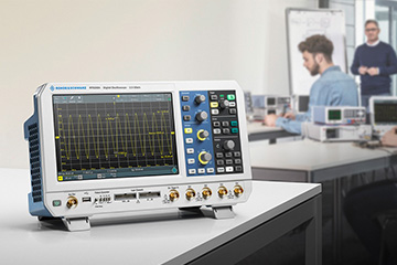
Oscilloscopes
Devices that convert electrical power to mechanical power run the industrial world, including pumps, compressors, motors, conveyors, robots and more. Voltage signals that control these electro-mechanical devices are a critical but unseen force. So how do you capture and see that unseen force?
Oscilloscopes (or scopes) test and display voltage signals as waveforms, visual representations of the variation of voltage over time. The signals are plotted on a graph, which shows how the signal changes. The vertical (Y) access represents the voltage measurement and the horizontal (X) axis represents time.
The graph on an oscilloscope can reveal important information:
Voltage and current signals when operating as intended.
Signal anomalies.
Calculated frequency of an oscillating signal and any variations in frequency.
Whether a signal includes noise and changes to the noise.
Most of today’s oscilloscopes are digital, which enables more detailed accurate signal measurements and fast calculations, data storage capabilities and automated analysis. Handheld digital oscilloscopes such as the Fluke ScopeMeter® Test Tools offer several advantages over benchtop models: They are battery operated, use electrically isolated floating inputs and also offer the advantage of embedded features that make oscilloscope usage easier and more accessible to a variety of workers.
Digital Multimeters
Welcome to the digital multimeter home page of Ken, the world leader in digital multimeters.
Ken offers a wide assortment of multimeters to fit every need. The digital multimeters have been categorized
Designs for everyday use
Ken’s digital multimeters also known as volt/ohm meters or VOMs combine several electronic measurement functions in one unit.
Our multimeters are designed to help you do your job faster, more efficiently and with greater accuracy, there is a model for every budget and application. Choose from hand held troubleshooters to ultra smart multi-meters packed with features, including the ability to log and graph data, as well as high-precision bench units in our showcase.
For help in selecting which meter fits your needs best, visit our updated and improved interactive selection guide.
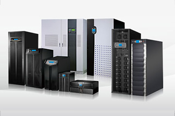
Power Supplies
A power supply is a component that supplies power to at least one electric load. Typically, it converts one type of electrical power to another, but it may also convert a different form of energy – such as solar, mechanical, or chemical - into electrical energy.
A power supply provides components with electric power. The term usually pertains to devices integrated within the component being powered. For example, computer power supplies convert AC current to DC current and are generally located at the rear of the computer case, along with at least one fan.
A power supply is also known as a power supply unit, power brick or power adapter.
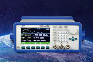
Function Generators
Function generators are items of test equipment that are able to generate a variety of simple repetitive waveforms. Straightforward signal generators such as RF signal generators or simple audio oscillators focus on producing a good sine waves, but in many cases other waveforms are needed. In addition to producing sine waves, function generators may typically produce other repetitive waveforms including sawtooth and triangular waveforms, square waves, and pulses. Another feature included on many function generators is the ability to add a DC offset. Often some of the low end function generators may only operate up to frequencies of possibly around 100 kHz as the various shaped waveforms are normally only needed at lower frequencies. However many other more comprehensive function generators are able to operate at much higher frequencies, often up to 10 or 20 MHz.
Frequency counters
Frequency counters are test instruments used in many applications associated with radio frequency engineering to measure the frequency of signals very accurately. These frequency counters and counter timers are widely used within a variety of areas to measure the frequency of repetitive signals, and also for measuring the time between edges on digital signals. Whilst the actual requirements and applications for RF frequency counters and timers are different, they use the same basic circuitry, with some simple internal reconfiguration and as a result sometimes RF frequency counters are also able to act as timers. Typically the very high RF frequency counters will not incorporate the timer capability.
Frequency Response Analyzers
Frequency Response Analyzer For The High Accuracy Transformer Analysis And Integrates The Sts And Td 5000 Family Test Sets. The Sfra 5000 Offers Both High Precision And Portability In A Single Package, Providing All The Accessories Required For Fast, Easy To Use, Reliable And Repeatable Measurements. Without The Need For A Pc To Compare Transformer Fingerprints, The Sfra 5000 Decreases Test Time Enabling The Engineer To Complete Testing In A Much Shorter Period Of Time Than Previously Possible. Sfra 5000 Is Provided With Its Own Embedded Software, Giving The Possibility To The Engineer To Zoom Into A Portion Of The Sweep In Order To Inspect Any Differences In The Plot In More Detail During Or After A Sweep.
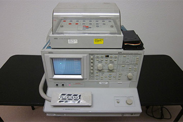
Programmable Curve tracers
Tektronix curve tracers offer power and versatility to test the DC characteristics of semiconductor devices. The 370B and 371B curve tracers combine a simple-to-use front panel, digital acquisition and display, and programmability to serve a variety of application needs. In the R & D lab, Tektronix curve tracers are used for characterization of new designs, extraction of SPICE parameters, failure analysis and data sheet generation. In manufacturing test, Tektronix curve tracers are used to verify device quality and process monitoring. They are also used for incoming inspection to verify device performance, perform failure analysis and match components.
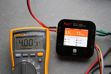
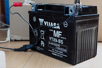
Battery Chargers
A battery charger, is a device used to put energy into a secondary cell or rechargeable battery by forcing an electric current through it. The charging protocol (how much voltage or current for how long, and what to do when charging is complete, for instance) depends on the size and type of the battery being charged. Some battery types have high tolerance for overcharging (i.e., continued charging after the battery has been fully charged) and can be recharged by connection to a constant voltage source or a constant current source, depending on battery type. Simple chargers of this type must be manually disconnected at the end of the charge cycle, and some battery types absolutely require, or may use a timer, to cut off charging current at some fixed time, approximately when charging is complete.
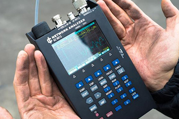
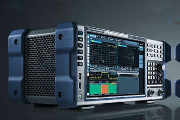
Network Analyzers
The vector network analyzer, VNA is a form of RF network analyzer widely used for RF design applications. A vector network analyser is a test system that enables the RF performance of radio frequency (RF) and microwave devices to be characterised in terms of network scattering parameters, or S parameters. The information provided by the vector network analyser VNA is then used to ensure that the RF design of the circuit is optimised to provide the best performance. Using an RF network analyzer in any RF design provides the RF design engineer with a view of the components and circuits that would not be possible with any other form of test equipment. In this way the vector network analyzer, VNA is an essential tool that RF design engineers should be able to use.
Although the name of the vector network analyser VNA is the most widely used name for this item of test equipment, sometimes it may be called a gain phase meter in view of the fact that they are able to measure both the gain, i.e. amplitude and also the phase of the device or item under test. Another name that is occasionally used is the Automatic Network Analyzer. However by far the most widely used is the name vector network analyser, VNA.
Spectrum Analyzers
What is a spectrum analyzer Spectrum analyzer types and technologies Superheterodyne / sweep spectrum analyzer FFT spectrum analyzer Realtime spectrum analyzer USB spectrum analyzer Spectrum analyzer tracking generator Specifications Spectrum analyzer operation Noise figure measurements Phase noise measurements Pulsed signal spectrum analysis
The suerheterodyne spectrum analyser which is also referred to by the name sweep or swept spectrum analyzer was the first form of spectrum analyzer to be used.
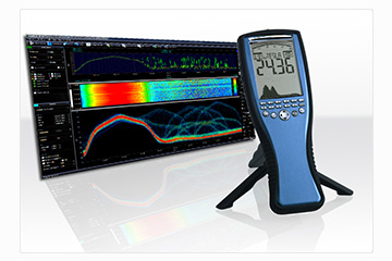
In essence the superheterodyne spectrum analyzer or sweep / swept spectrum analyzer is a form of radio receiver with a display at the output indicating the output level. The receiver is tuned or scanned over the required range and the filters are chosen to accept the required signal bandwidth. The spectrum analyser uses the superhet principle used in many radio receivers as the underlying principle on which its operation depends. The superhet principle uses a mixer and in addition to a locally generated or local oscillator to translate the frequency.
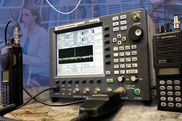
Radio Communication Test Sets
Radio amateurs have been praised on many occasions for the way in which they have responded to emergency situations. Many times the two way radio communications service they have provided has saved lives or enabled people be helped more quickly of effectively. While the name amateur radio or ham radio often seems to imply a lack of expertise, this is not the case, and people in authority have often commented that the service offered by radio amateurs is far from "amateur" service, but instead it is very professional. They are able to provide two way radio communications systems in a way that even the professional services are unable to do under very exacting conditions.
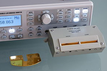
LCR Meters
the key points the LCR meter and how it can be used to measure inductance, capacitance and resistance.
LCR meters are used to measure the inductance, capacitance, and resistance of components.
The LCR meter takes its name from the fact that the inductance, capacitance and resistance are denoted by the letters L, C, and R respectively.
A variety of meters are available. Simpler versions of LCR meters provide indications of the impedance only converting he values to inductance or capacitance.
More sophisticated designs are able to measure the true inductance or capacitance, and also the equivalent series resistance of capacitors and the Q factor of inductive components. This makes them valuable for assessing the overall performance or quality of the component.